
DIY ESPHome Light Sensor
Easy and customizable sensor for Home Assistant
Some time ago I worked on a little project to craft a light sensor for Home Assistant using ESPHome.
I made a video out of the process and uploaded to Youtube:
ESPHome Code
Typical for ESPHome the code is really minimal:
esphome:
name: lightresistorminid2
friendly_name: LightResistorMiniD2
esp8266:
board: d1_mini
# Enable logging
logger:
# Enable Home Assistant API
api:
encryption:
key: "<KEY>"
ota:
password: "<PASSWORD>"
wifi:
ssid: !secret wifi_ssid
password: !secret wifi_password
sensor:
- platform: resistance
sensor: source_sensor
configuration: DOWNSTREAM
resistor: 470kOhm
name: Resistance Sensor
unit_of_measurement: "lx"
device_class: "illuminance"
state_class: "measurement"
accuracy_decimals: 1
filters:
- calibrate_linear:
method: exact
datapoints:
- 10.0 -> 800.0
- 100.0 -> 600.0
- 9000.0 -> 50.0
- 32729.0 -> 30.0
- platform: adc
id: source_sensor
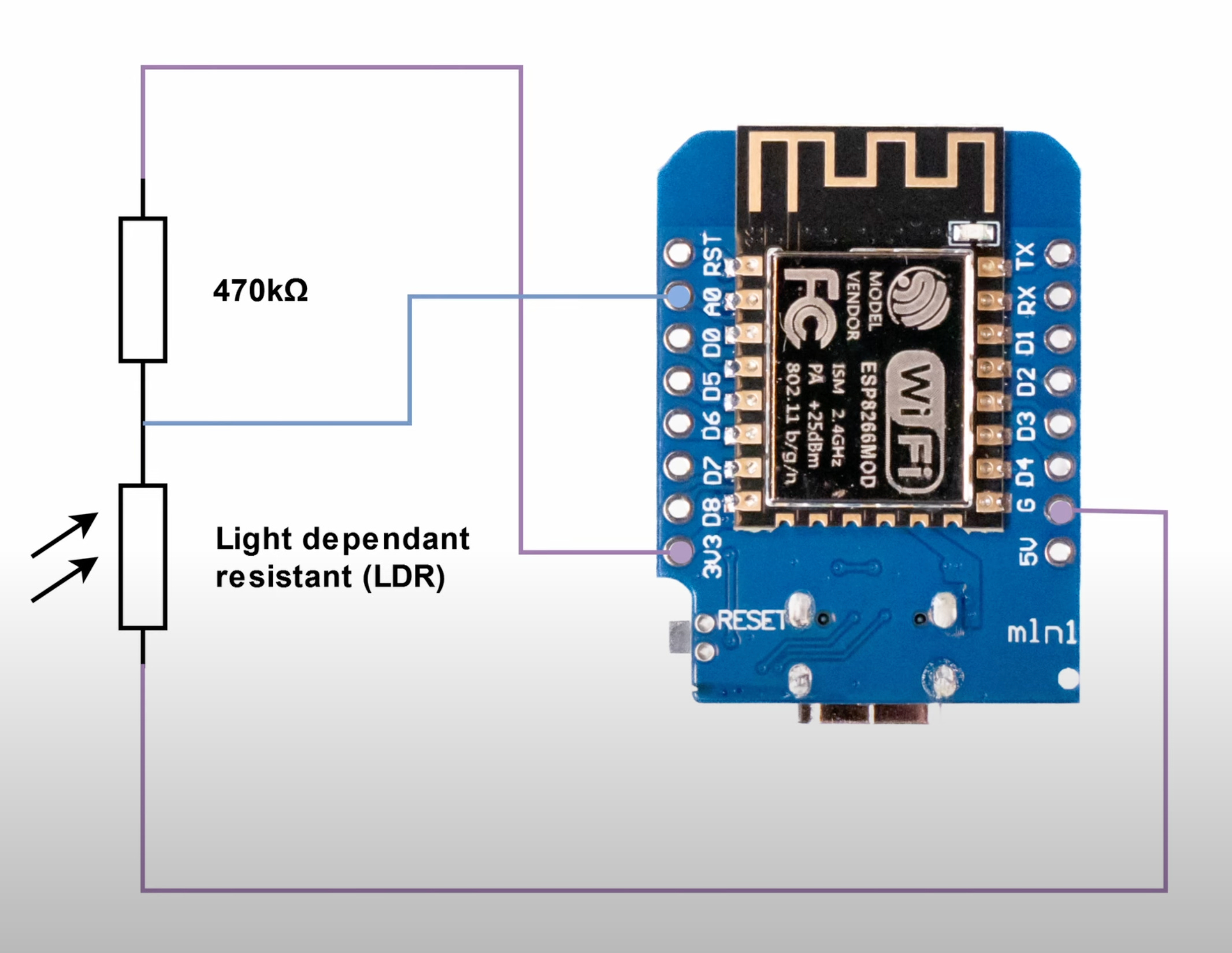
pin: A0LDR Selection
Some time ago there was a question by a viewer under this video, which I wanted to answer for along time, but always forgot.
Therefore, as an apology, let’s look at what this was about..

Which is the correct LDR and what resistor to chose?
As always in life: it depends :)
An LDR is in many dimensions non-linear and it all comes down to the situation it is going to be used in. Different parameters influence the decision:
operational temperature (see the graph below)
expected light intensity (may vary heavily )
measured wave length
See this datasheet of an GL5528 (Sparkfun):
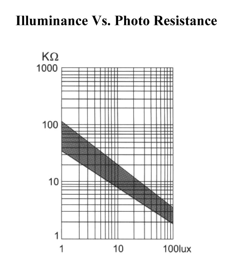
From this graph we can see that the resistance with 100lux is between 2-4 kOhms (gray area at 100lux x-line). A brightly lit room has around 500lux (taken from here), which will result in about 1kOhm resistance.
With this info it is then crucial to optimize for the relevant luminance levels the sensor is meant for. If there is a need for high resolution by the ADC for a wide range of brightness levels, it might make sense to chose an accompanying R that is not much higher than 1kOhms.

For better understanding, I have created a graph animation on desmos.com for this LDR for the range between 1lux (100kOhm) and 500lux (approx. 1kOhm), which you can play with yourself under
https://www.desmos.com/calculator/gvnvheoat2
You can use this page to estimate the expected voltage outcome of the voltage divider of R and R_ldr by moving the slider for R, while the R_ldr is animated for its particular range.
This can then be used to chose the values optimally to leverage as much as possible of the 0-3.3V span of the ADC of the ESP module - otherwise it will jump significantly between relatively small changes in brightness due to quantisation effects.
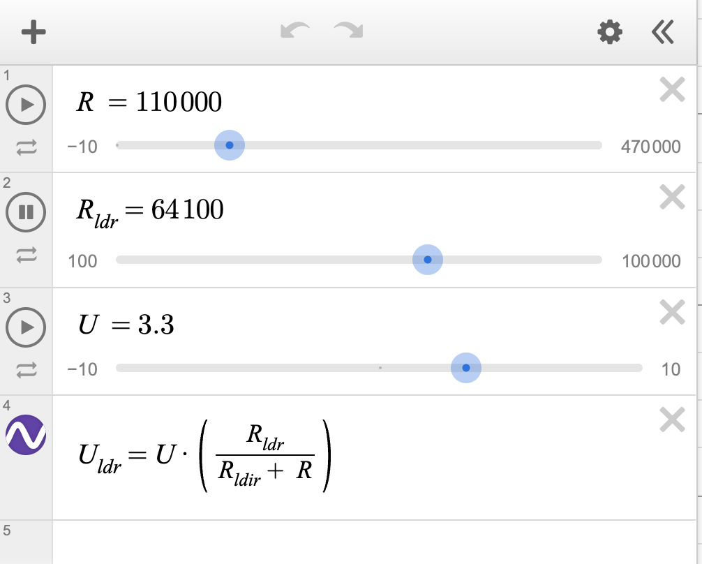
If you chose a different LDR make sure to adapt these values (check the datasheet).
Hope this was helpful.
Cheers, Buschi.